Chiller Clearances vs. Efficiency
Making the Most of Air-Cooled Chiller Efficiency
Introduction
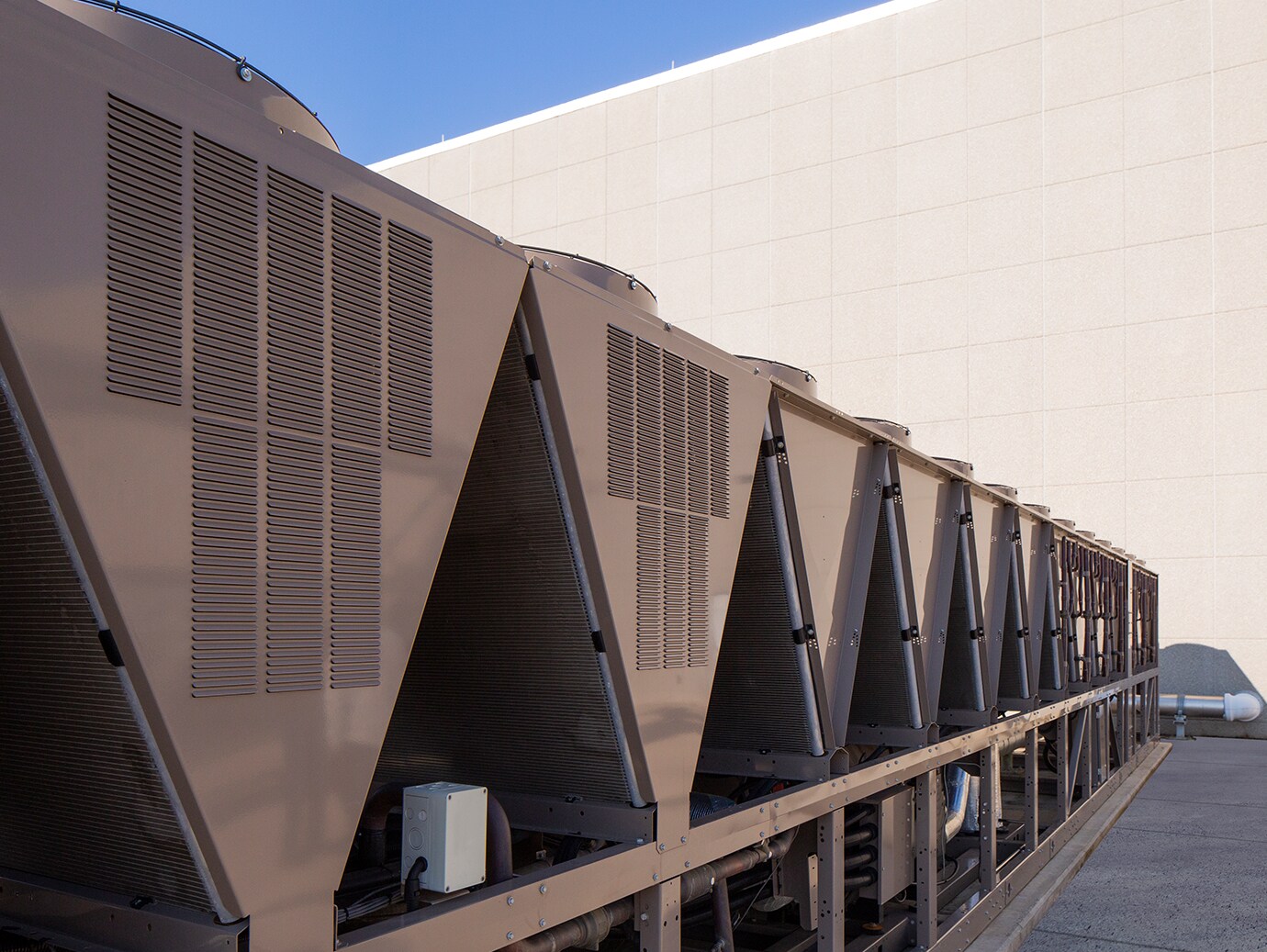
In most installations, the chiller is the single largest energy-consuming component of an entire facility. For that reason, decreasing a chiller’s efficiency even slightly can result in a significant impact on energy costs, not to mention long-term maintenance and reliability. In air-cooled chillers, one of the largest contributors to efficiency – or the lack thereof – is proper airflow.
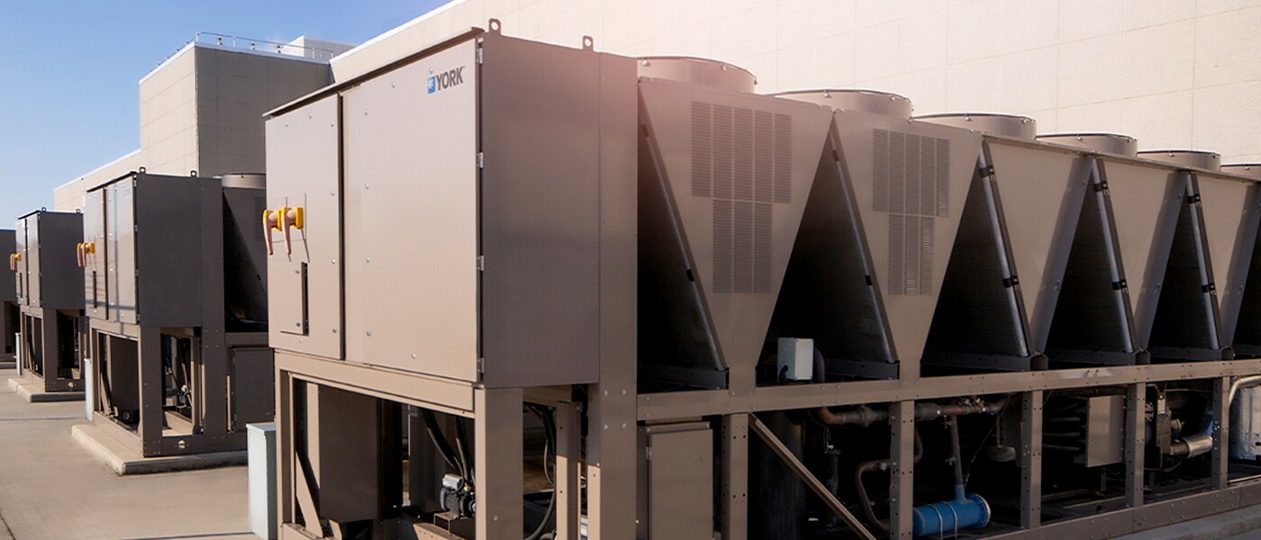
Johnson Controls has established guidelines for the placement of YORK® air-cooled chillers when next to each other or next to walls, while still allowing adequate airflow to the units. When chillers are used in situations that result in restricted airflow due to close spacing, multiple chiller units or other obstructions, increased power consumption and loss of capacity may occur. This article, and a more in-depth application guide which you can request, will summarize the effects of these restrictions to help inform decisions regarding chiller unit placement.

Recommended Clearances
While exact clearances can vary by model, for our example, we will use the factory-recommended minimum clearances for a YORK® YVAA chiller. These include side to wall: 6 ft (1.8 m), rear to wall: 6 ft (1.8 m), control panel end to wall: 4 ft (1.2 m), top: no obstructions and finally, the distance between adjacent units: 10 ft (3 m).
Case Study Findings
Several factors can affect the capacity and power requirements of an air-cooled chiller. However, for purposes of this study, we limited the variables to include the specific obstructions outlined below. The tests were conducted on YORK® YVAA VSD screw and YORK® YLAA scroll chillers. The results for both units were similar, with the effects of the obstructions increasing on units with higher fan counts.
Results Summary
Any potential benefits derived from a deviation from minimum factory clearances should be carefully weighed versus the performance decreases outlined here in.


